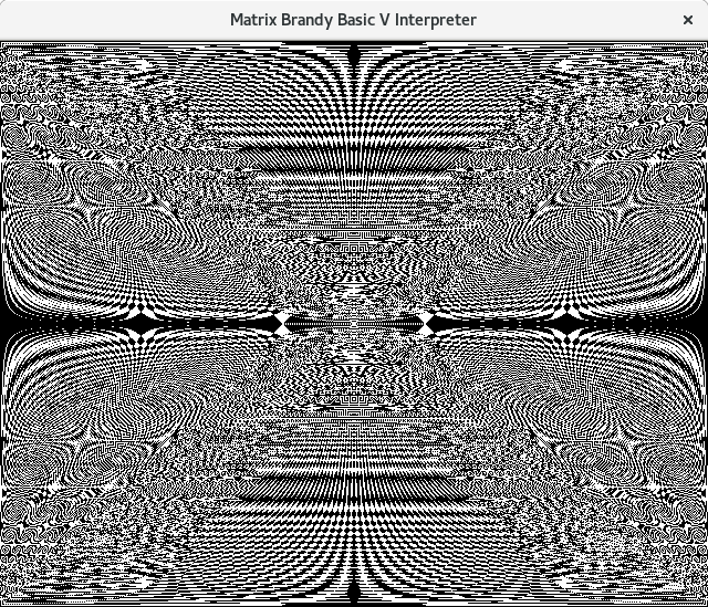
Read below how patterns like this are made.

In the years 1986 to 1988 I used the Sinclair ZX-Spectrum as my primary computer. This machine invited you to experiment with simple line drawing programs. Many magazines published simple programs that showed interesting visual effects (including use of the OVER keyword), but I did not see anything like the program I am showing here, so I did discover it independently of any others who might have come op with the same idea. I am not claiming a copyright on this pattern, it's just math, a bit like the Mandelbrot fractal. I do expect that others discovered this pattern before. Maybe it even has a name.
The ZX-Spectrum was a very popular home computer in the 1980s, especially in Europe. It had a bitmapped screen of 256 by 192 pixels. On top of that, each cell of 8 by 8 pixels had an attribute byte with a foreground and background colours, so you could create colour pictures, but with the restriction that each 8x8 cell had only one foreground and one background colour. For the purpose of this article, we stick to monochrome: background colour is white and foreground colour is black.
ZX Spectrum BASIC had simple commands to draw points, lines and even circles, so fun was at your fingertips at the very moment you started the machine. This unlike the Commodore 64 where you first had to study the POKE commands to get the video chip into bitmapped mode and then you had to do a PEEK and POKE for every single pixel you wanted to draw (with complex bit manipulation and calculation of the address). By the time you knew how to draw a line, let alone a circle, you were almost a master programmer. The BASIC commands could draw in an area of 256 by 176 pixels (not 192), as the bottom two rows were reserved for error messages and commands you typed.
Apart from the line drawing commands, you had other commands to control the foreground and background colours of whatever you were printing (called INK and PAPER), to make certain characters flash or extra bright (FLASH and BRIGHT commands), to draw in inverse mode (called INVERSE) and in "overprinting mode" (called OVER). The latter command produces the interesting effect around which this article revolves. All these commands could also occur as extra parameters in PRINT, PLOT and DRAW commands (and then they would only affect that single command). With the OVER command, any command that displayed information on the screen would invert any bit on the screen instead of setting it to '1'. Therefore it is an XOR operation between the bit map it wants to draw and the pixels that are already on the screen.
Other microcomputers, for example the Acorn Atom (and the BBC Micro, the Electron and the Archimedes) had easy to use line drawing commands too, including the XOR mode plotting we just discussed. We will see this later.
While this overprinting technique could be used to print accents over letters to get accented letters (as was shown in the ZX Spectrum manual), this did not work very well. But the technique was quite useful for another purpose. When you draw a shape in this mode over an existing picture, you can restore the original picture by drawing the exact same shape again (it would invert all bits again that the original operation had inverted). This made it ideal for temporary objects that were shown over a background picture and also for moving objects, As a bonus the temporary or moving object would contrast with whatever background it was shown on. The technique was most useful on monochrome bitmapped screens.
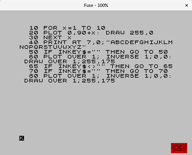
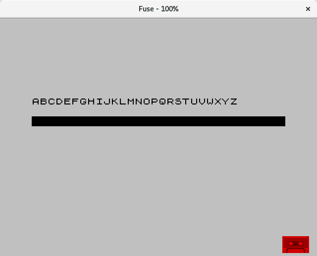
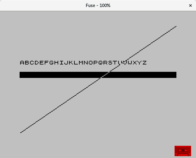
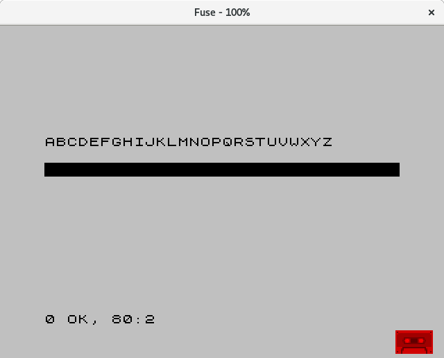
The program below (named "overeffect") shows how to draw a line with overprinting on the ZX-Spectrum and how this line will disappear without a trace when you draw the exact same line again. Lines 10-30 draw a horizontal bar and line 40 displays some text above it. The first screenshot shows what this looks like. Line 50 waits for a key to be pressed and then line 60 draws a diagonal line from bottom left to top right as shown in the next screenshot. Where the line crosses the bar, you see that the pixels are white (black pixel over black pixel becomes a white pixel). Also the text is partially erased by the line. Line 65 and 70 wait for the key to be released and wait for another keypress. Next in line 80 the same line is drawn again and it disappears without a trace and the picture is exactly as it was before the line was drawn. The horizontal bar is solid again and the letters U and V in the text are also restored.
Also note that lines are one pixel wide and diagonal lines look jagged. There is absolutely no antialiasing. The pattern of this algorithm depends on lines being drawn in exactly this way.
Now y
The procedure is quite simple. You draw a line from every position at the bottom of the screen to every position at the top of the screen. So if your screen is 256 pixels wide, you draw 256 lines from the leftmost pixel at the bottom to each position at the top, you draw 256 lines from the second leftmost pixel at the bottom to each position at the top until you draw 256 lines from the rightmost bottom position to each position at the top. In total you draw 256 x 256 = 65536 lines. Of course you draw all the lines in XOR overprint mode (or whatever it is called on your system).
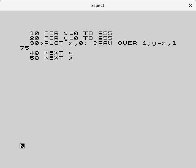
The program has two nested loops: X iterates over all bottom positions and Y iterates over all top positions. Note that the DRAW command on the ZX-Spectrum uses relative coordinates, hence you have to specify y-x if you want to draw from x to y. This is the program on the ZX-Spectrum. You can download this tape image overeffect.tap (right-click to download) to run both this program and the "overeffect" example in your favourite ZX-Spectrum emulator.
  10 FOR x=0 TO 255
  20 FOR y=0 TO 255
  30 PLOT x,0:DRAW OVER 1;y-x,175
  40 NEXT y
  50 NEXT x
This is what it looks like on the screen.
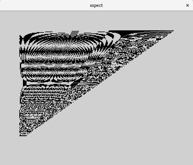
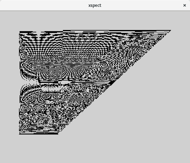
See the pattern on the Spectrum at various stages of completion. Really, you should see this in action and see the pattern develop, this is more than half the fun. On the Spectrum this took over 50 minutes to complete. My PC (when running Brandy) takes just over 7 seconds for a pattern with the same dimensions.
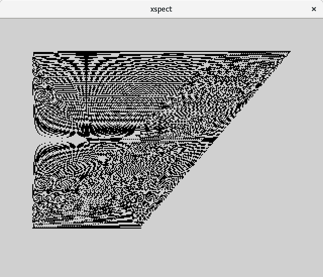
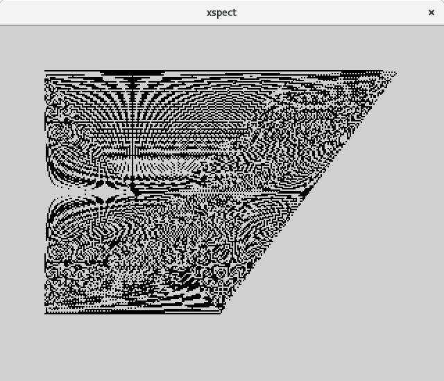
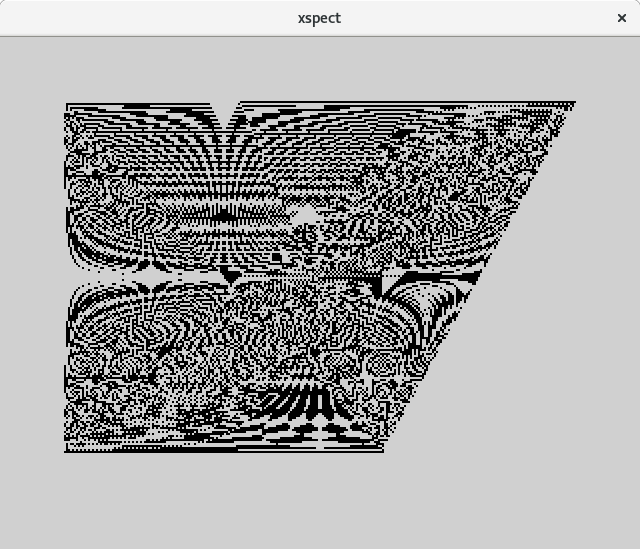
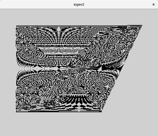
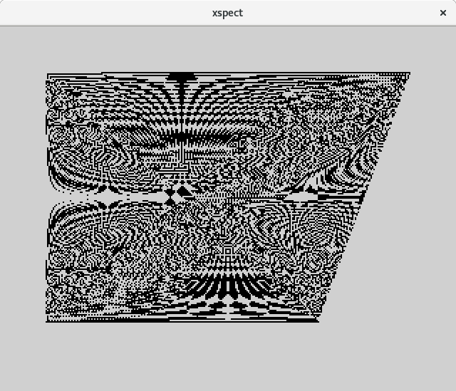
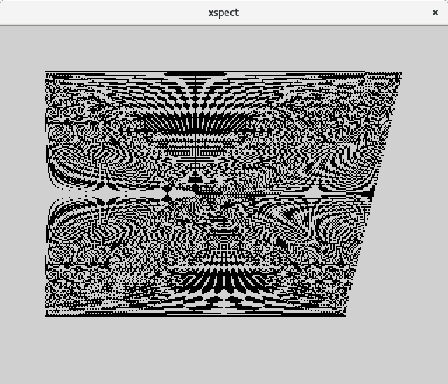
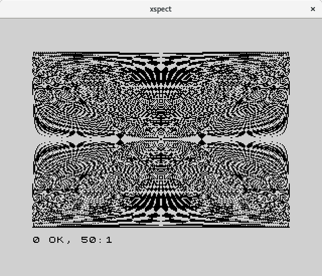
The picture at very the top of the page was generated by Brandy BASIC, an open source implementation of BBC-basic, using this program.
MODE 18: REM 640x512 monochrome
REPEAT
  INPUT "Width (1-640)";W%
UNTIL W%>=1 AND W%<=640
REPEAT
  INPUT "Height (1-512)";H%
UNTIL H%>=1 AND H%<=512
CLS
T%=TIME
FOR X%=0 TO 2*W%-1 STEP 2
  FOR Y%=0 TO 2*W%-1 STEP 2
    PLOT 4,X%,0:PLOT 6,Y%,2*H%-1
  NEXT Y%
NEXT X%
T%=TIME-T%
x$=GET$
CLS:PRINT"This took ";T%/100;" seconds to draw."
This program does essentially the same thing as the ZX-Spectrum
program, but you generate patterns of any dimension (up to the pixel
resolution of the screen). Further it displays the elapsed time, but
this is not essential functionality.
The listing speaks for itself, except for the PLOT commands. PLOT 4 means move the graphic cursor to an absolute position (without drawing anything) and PLOT 6 means draw a line to the specified absolute position with the inverse colour of what is on the screen. (PLOT 5 would draw the line in the foreground colour and PLOT 7 would draw it in the background colour). The X and Y coordinates always run from 0 to 1279 and from 0 to 1023 respectively, regardless of the actual screen resolution. As the actual screen resolution is really half of this (640 by 512), the FOR-loops step by 2 to twice the specified width in pixels and the height of the pattern is also multiplied by 2.
The colour of each pixel in the end result will depend on the number of times the line drawing algorithm has visited that particular pixel. If this number is odd, the pixel will be set (foreground colour), if this number is even, the pixel will be cleared (background colour).
All lines are drawn using the Bresenham's line algorithm. This draws a continuous line of exactly 1 pixel wide in which the straight steps and diagonal steps are divided as equally as possible.
If the absolute value of the slope of a line is less than 1, the horizontal dimension of the line is larger than the vertical dimension and the Bresenham algorithm will draw exactly as many pixels as the horizontal dimension and it will use horizontal steps interleaved with diagonal steps. Let's call these horizontal mode lines.
If the absolute value of the slope of a line is more than 1, the the vertical dimension of the line is larger than the horizontal dimension and the Bresenham algorithm will draw exactly as many pixels as the vertical dimension and it will use vertical steps interleaved with diagonal steps. Let's call these vertical mode lines.
If the absolute value of the slope is exactly 1, the Bresenham algorithm will use diagonal steps only, regardless of the mode (horizontal or vertical) it is working in.
Suppose we have a pattern of W pixels wide and H pixels tall. If the pattern is taller than it is wide or if it is exactly square (H ≤ W), all lines will be vertical mode lines and each line drawn is exactly H pixels. The number of lines drawn is W*W, so the total number of pixels drawn is W*W*H. As the number of pixels is W*H, the average number of times a pixel is visited is W*W*H/W*H = W.
If W is larger than H, some of the lines will be drawn in horizontal mode and the resulting pattern will be more complex.
So let's start to draw the pattern and see what happens.
As we have seen, some pixels will only be visited twice, so other pixels must be visited more often than the average. It might be interesting to compute a height map indicating the number of times a pixel was visited, instead of just the odd-even pattern.
One would expect the pattern to be fully symmetric. After all you are drawing lines from every point in the bottom row to any point in the top row, which intuitively feels like there should be both top-bottom and left-right symmetry.
At first glance the patterns on this page may appear to have this symmetry, but if you look more carefully, you will see that this is not the case. There are differences between the large pattern shown at the top of this page and the smaller pattern generated by the ZX-Spectrum. One difference is that the pattern at the top has more pixels (640x512) than the pattern of the ZX-Spectrum (256x176). Another difference is that the foreground colour in BBC BASIC is white by default and the one on the ZX-Spectrum is black. Therefore the odd pixels in the pattern at the top of the page are white, while those in the other pattern are black. But the most striking difference between the patterns is the the top pattern is top-bottom symmetric (and not left-right symmetric), while the Spectrum pattern is left-right symmetric (and not top-bottom symmetric).
This difference is symmetry is caused by the way the line drawing algorithm is implemented in both BASIC interpreters. If I draw a 256x176 pattern in Brandy Basic, I will get top-bottom symmetry and left-right asymmetry, just like the big pattern. As far as I understand, ZX-Spectrum will always draw the line from the source point to the destination point. As the source point of each line is at the bottom and the destination point is at the top, each line will be drawn from bottom to top. On the other hand, Brandy Basic appears to draw each line from left to right, even if the destination point is to the left of the source point. This will make a difference and the inherent asymmetry in some lines drawn using the Bresenham algorithm will cause the asymmetry in the end result one way or the other.
Suppose I want to draw a line from bottom left to top right that is five pixels wide and 4 pixels high. It can be done in two ways, as shown in the figure below.
For this line we have to make three diagonal steps and one horizontal step. In the first pattern the order is D,H,D,D and in the second pattern the order is D,D,H,D. The standard Bresenham algorithm would pick D,H,D,D and it would draw the first pattern if the line is drawn from bottom left to top right and it would draw the second pattern if the line is drawn from top right to bottom left .
It turns out that when the larger dimension of a line is even and the smaller dimension is odd, then the decision steps in the line drawing algorithm do not form a palindrome and the resulting pixel pattern will depend on the order in which you draw the line.. When you draw two lines, one from bottom left to top right and one from top left to bottom right, they will form a cross, which would be both top-bottom and left-right symmetric, if these were ideal mathematical lines. But with lines drawn by the Bresenham algorithm, the resulting shape will depend on the order in which the lines are drawn. For a five by four pattern, the resulting shape will symmetric by accident, but for a 7 by 4 pattern, the pattern will be either bottom-top symmetric of left-right symmetric, but not both. See the figures below.
The green blocks belong to the first line, the red blocks belong to the second line and any yellow blocks are visited by both lines (they will be cleared when we draw the pattern). The topmost pattern is the result when both lines are drawn from left to right (and it has top-bottom symmetry) while the bottom pattern is the result when both lines are drawn from bottom to top (and it has left-right symmetry).
So finally we have demonstrated how the resulting patterns will go asymmetric. On the other hand, if the larger dimension of a line is even, the order in which the line is drawn is irrelevant (results in the same pixels being drawn). if we both a line from bottom left to top right and a line from bottom right to top left, the resulting cross will have a pixel pattern that is both left-right and top-bottom symmetric.
So if the height of the pattern H is even, all vertical-mode lines will not create asymmetric patterns. So if we further ensure that W ≤ H (the pattern is taller than it is wide or it is exactly square), there will only be vertical-mode lines and the entire pattern will be symmetric. I did observe this while running the program under Brandy. The pattern with W=256 and H=176 is asymmetric, but W=176 and H=256 creates a fully symmetric pattern. Square patterns are symmetric if the size is even. I did observe asymmetric patterns with many odd-sized squares (the smallest is a 5 by 5 square). Not all patterns with W > H or where H is odd are asymmetric though, as least I did not observe it by visual inspection. Patterns where W and H contain large powers of 2 seem to be more often asymmetric, for example 640x512, but I have not seen the system yet.
I am planning to write a program to analyze this pattern and its asymmetries more systematically. Asymmetry can best be checked by a program and it can even be quantified by counting the pixels that are different when you overlay the pattern with its mirror image. I will trade the fun of BASIC for the speed of C. I do not need to print each pattern on the screen as it is drawn, I can just generate and analyze it in a 2-dimensional array. If I want to see a pattern, I can always export it as a pbm file. One day you will see the C program and the results of the analysis.